Function
- Motor driven, variable orifice, restrictive type, hydraulic flow control, non-pressure compensated. Pressure balanced, bi-directional flow.
Operating Pressure
- 3000 psi maximum differential
- Consult factory for higher operating pressures
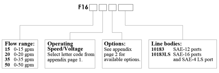
Flow Ranges
Based on 100 PSI pressure differential with valve fully open. See pressure drop curves for additional application data
- 15 0-15 gpm (Equivalent to Ø.25” orifice at full open)
- 20 0-20 gpm (Equivalent to Ø.35” orifice at full open)
- 35 0-35 gpm (Equivalent to Ø.49” orifice at full open)
- 50 0-50 gpm (Equivalent to Ø.56” orifice at full open)
- Custom ranges are available upon request
Voltage
- 12 & 24 VDC
Construction
- Cage, body and spool: Steel, exposed parts plated
- Motor housing assembly: Anodized aluminum
- Standard line bodies are aluminum
- Steel bodies are available upon request
Seal Material
- Buna N and polyurethane standard
- Viton optional
Current Draw
(only while adjusting)
- 0.8 amp when powered at 12 volts
- 1.0 amp when powered at 24 volts
Internal Leakage
- 5 cubic inch per minute per 1000 psi
Temperature
- -40 to 120°C